Screen in less engineering time
Compare published specifications and rule out poor fits before starting separate supplier conversations.
3D vision for robot bin picking
Share the part, how it arrives and where it must go. We’ll outline which vision method can guide the robot and what to check for the pickup, motion and placement.
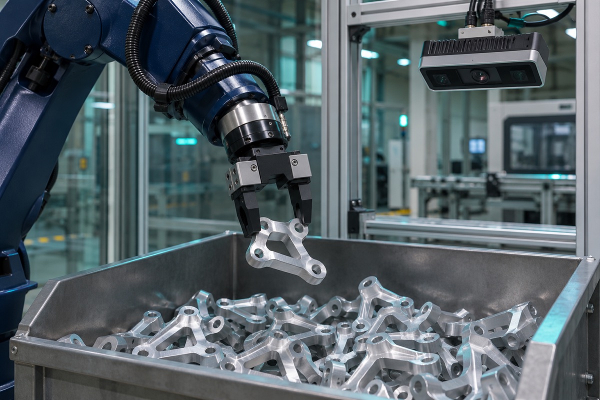
Engineering decision support for industrial vision
We help engineering and procurement teams decide which approach fits a part, a tolerance and a production line. We compare the options, explain what would rule each one out, and identify which test could change the decision.
Our research on Chinese industrial vision suppliers gives the recommendation a concrete basis: model specifications, application examples and documented limitations. We flag what is known, what depends on your samples and what a supplier still needs to confirm.
The handling example compares the published working ranges and fields of view of the Mech-Eye PRO S-GL and TransferTech Laser L V2S, then identifies the bin coverage, gripping and placement tests to run.
See an example review →See how the robot cell fits together →November 2026 research: 805 deduplicated leads screened against the application scope, 42 candidate sites reviewed in more depth and 133 hardware model records indexed from manufacturer materials. The index includes 106 area-scan models from one manufacturer.
We also mapped nine public support, testing and integration leads in the US and Japan. For a live project, we check which provider can take the work and confirm scope, availability and responsibility before any handoff.
Get a route shortlist, the evidence behind it and the next test from one project brief.
Compare published specifications and rule out poor fits before starting separate supplier conversations.
The deep-bin example compares two camera options against working distance and coverage, then identifies where the gripper and fixture need separate tests.
Compare equipment, fixtures, software, integration and support on the same scope. Spot scope differences before you decide which quotes to pursue.
Share the part, acceptance rule and line constraints once. Use the same summary to brief your team, request quotes and plan a sample test.
Identify where the project needs depth imaging, pose correction, gripper design or robot integration.
Use working distance, field of view and installation geometry to screen 3D cameras from Chinese manufacturers.
Check the full cell against actual parts, placement tolerances and sustained cycle time.
Compare how each task works, what the manufacturer materials support, and what to verify with real parts.
Choose by what vision must resolve. If vision must correct the pose at the destination, choose alignment. Otherwise, choose bin picking when vision must locate a pickable part in loose supply, or transfer when a tray or fixture already presents the part.
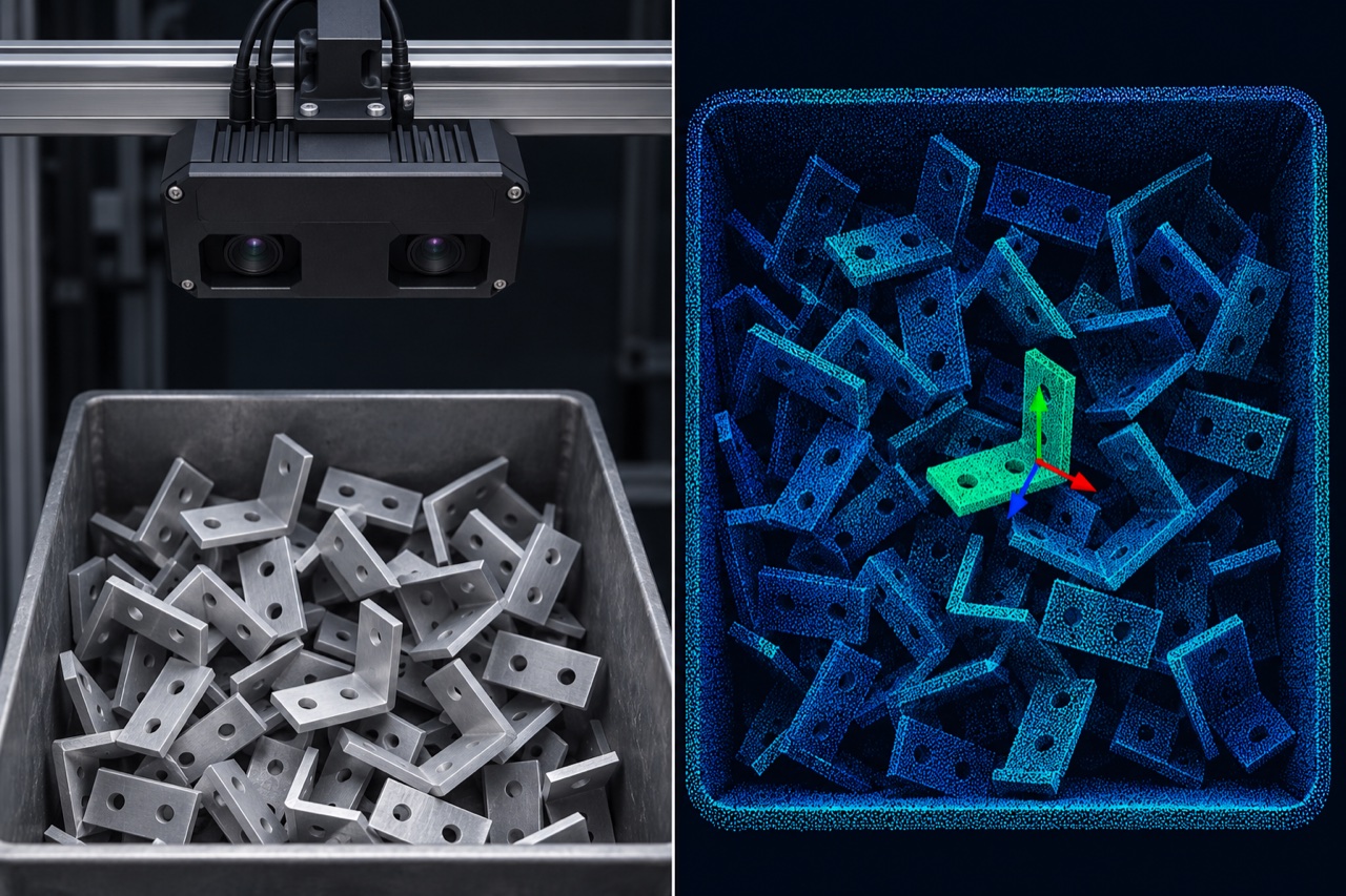
Scan the pile from above.
Identify an exposed part and estimate its pose.
Plan a clear approach and lift one part.
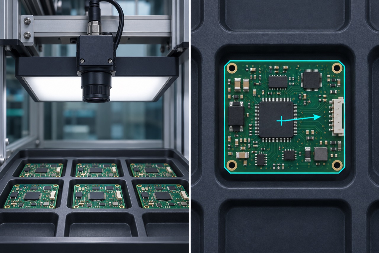
See which pocket is occupied.
Estimate position and angle from the board outline.
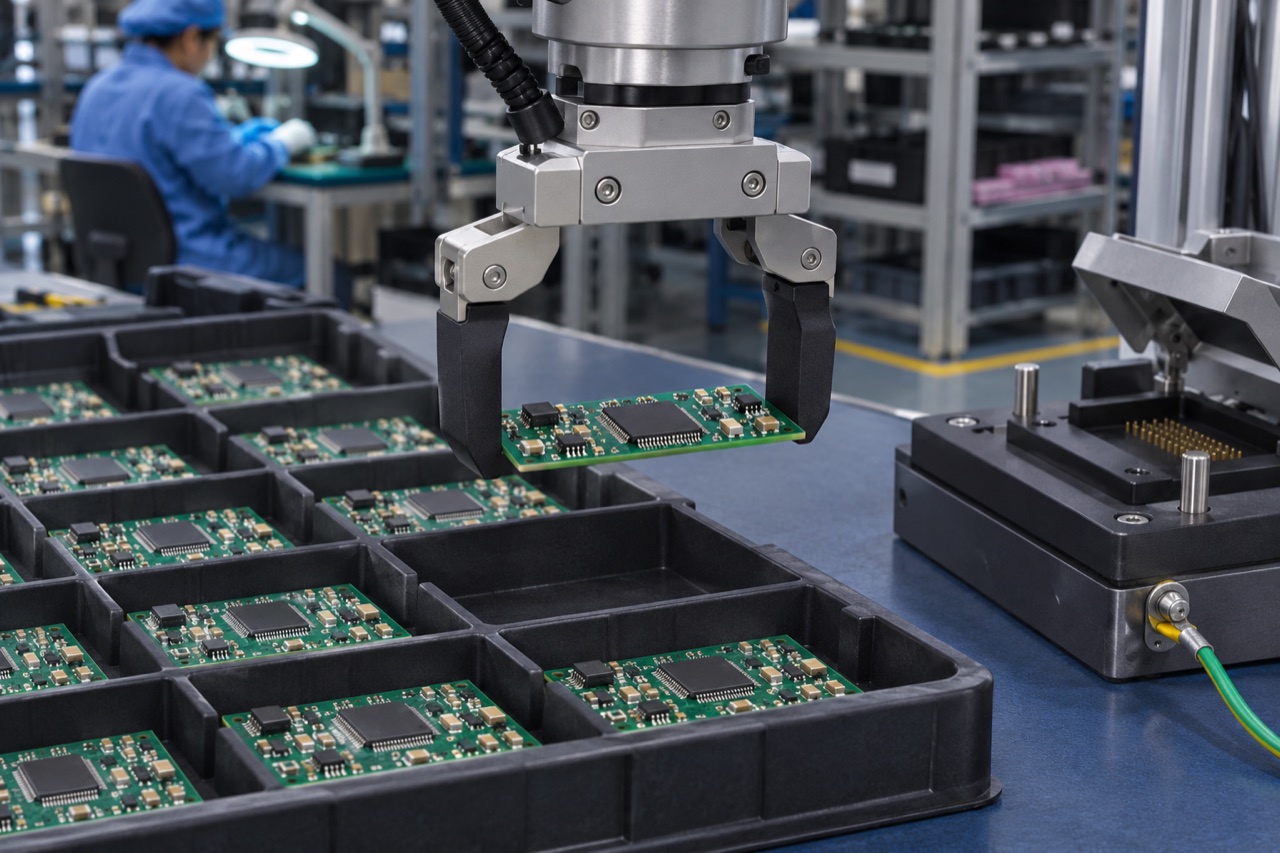
Adjust the pickup pose and move the board.
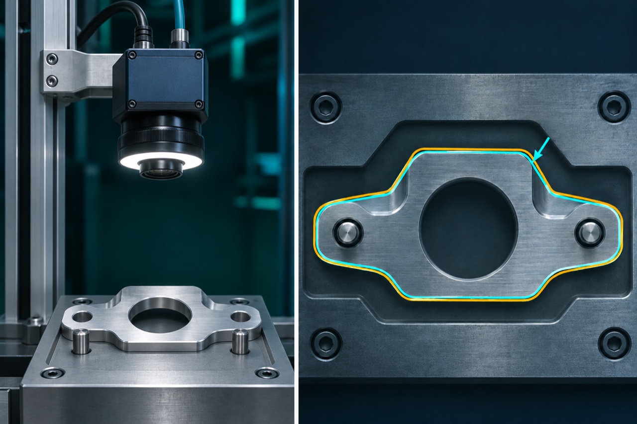
Locate the part relative to the fixture.
Compare measured and target positions.
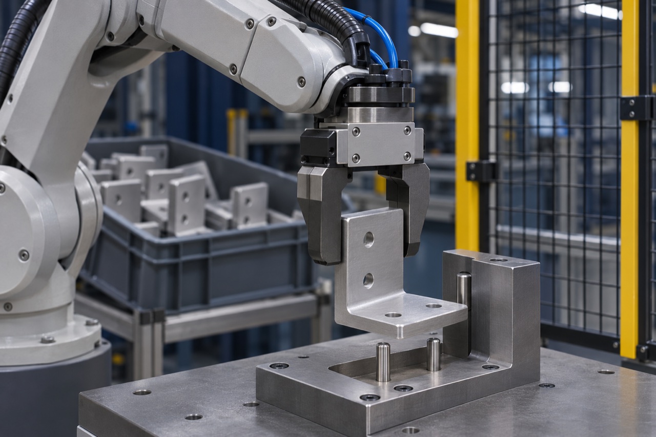
Update the robot pose and verify seating.
Published specifications support initial selection. Confirm application performance, lead time, local support and integration scope with the supplier or integrator after reviewing your parts and site requirements.
Start with how the part arrives and what the receiving station needs from the robot.
Separate the camera view, the coordinate transform, the grasp and the handoff. A strong point cloud is useful only when these stages work together.
Place the camera so it can see relevant parts from the top layer down to the bin floor. Check what the wall and other parts occlude.
What we need to know Bin dimensions, mounting height, working distance and field of view at both fill extremes.
Estimate a pick pose from the image or point cloud, then transform it into robot coordinates using hand–eye calibration. Define the response when no valid pose is available.
What we need to know Robot/controller model, camera mounting arrangement, calibration and interface.
Check gripper contact and clearance before commanding the robot. Agree when the cell can retry, rescan or ask for operator help.
What we need to know Part weight, allowed contact surfaces, obstacle clearance and recovery behavior.
Align the part to the receiving fixture. Verify that it seats in the required pose and track failed placements or manual interventions over repeated cycles.
What we need to know Fixture datum, placement tolerance, success rate and sustained cycle time.
How far is the camera from the highest part and the bin floor? The screened cameras cover different working ranges. Mech-Mind’s published sheet-metal example also separates pose estimation from robot path planning, so we would test visibility, grasp and clearance as distinct risks.
Example: we compare two 3D cameras against the distance from the mount to the highest part and the bin floor. This screens out candidates before you spend time on a demo or quote.
Mech-Eye PRO S-GL stays within its published 0.5–1.0 m range. TransferTech Laser L V2S starts at 1.2 m, so it falls outside its recommended range at this mount.
TransferTech Laser L V2S stays within its published 1.2–3.0 m range. PRO S-GL is beyond its published range. The actual bin footprint still needs to fit the field of view.
Check coverage at both fill heights with representative parts. Confirm the robot interface, calibration setup, lead time and local support. Verify actual pick and placement on samples.
Distances above are illustrative mounting scenarios. Ranges are published model specifications. Results and delivery are confirmed for each application.
Share your bin, part and robot →Overlapping metal parts must be taken from a bin and placed into a fixed nest. Reflective surfaces, clearance near the walls and remaining parts at the bottom are the main unknowns.
Example: A camera can see the part at the top of a bin and still miss pieces at the bottom. Check both positions before choosing the camera.
Request a sample-based feasibility test when camera coverage, robot reach and candidate gripping surfaces have been screened.
Separate the 3D camera and software, robot and gripper, fixture, controls, guarding and line integration. Identify who owns calibration and ongoing support.
Share the same parts, fill states or tray variants, required orientation, robot model and target cycle time with each bidder.
Agree how to count retries, empty picks, placement failures and manual intervention. Confirm delivery, commissioning and local service responsibilities.
Choose the level of support that fits your decision.
Screened supplier pool and industry contacts
We match your part, process and qualification needs against our screened pool of Chinese suppliers and industry contacts. We explain why candidates fit, flag gaps and help with introductions or quote requests where appropriate.
Planning estimate: 2–3 business days for an initial sourcing reply once we have enough detail to assess the request.
Research, validation and on-site discussions
We help you compare technology routes, assess the Chinese supplier market and decide what to validate before committing. If an in-person visit would help, we can shortlist sites, prepare a technical agenda and coordinate supplier meetings or factory visits, subject to availability.
Planning estimate: 5–10 business days for a focused advisory report after scope and inputs are agreed. We confirm the delivery date before you commission work.
Share your project and we’ll confirm the scope, timing and any fees before work begins. Equipment, samples, travel and third-party testing are quoted separately where applicable.
Discuss your project →Share your application and work email. Our team will review the details and follow up with the next questions or evaluation steps.
See a sample review →Start with the part, where it comes from and where it must go. We can identify the first vision or handling test and the camera, robot and integration questions that remain.
Start with the part, how it arrives and where it must go. Add the robot model, preferred gripper or target cycle time if known.
Yes. Camera screening covers usable depth and field of view. A cell review also considers the gripper, robot path, fixture and exception handling.
The first review can identify the work to evaluate. Test access, robot compatibility and integration responsibility are confirmed with the relevant company for each application.